Home / Capabilities
Two layers to thirty-six — and the awkward boards in between.
One plant, all four capability families and an engineering team that reads stack-ups for a living. If your board needs a hybrid dielectric, a 3-stage HDI build and a castellated edge in the same order, it stays in one factory.
At a glance
| Parameter | Range |
|---|---|
| Layer count | 2 – 36 layers (4, 6, 8, 10 and high-layer-count builds in routine production) |
| HDI | 1–3 stage builds, laser-drilled microvias, blind and buried vias, resin-plugged via-in-pad |
| Base materials | FR-4 (Shengyi, ITEQ, Nanya), high-Tg, halogen-free, thick copper, aluminium/metal core, ceramic, PTFE, Rogers RO4003C / RO4350B / RO3003 / RO4835, Taconic, IT180 |
| Surface finish | Lead-free HASL, ENIG, ENEPIG, immersion tin, immersion silver, hard gold, OSP |
| Solder mask & legend | Taiyo and Guangxin inks, matte or gloss, white/black/green/blue/red, ink-jet legend |
| Vias & structures | Blind, buried, via-in-pad with resin plugging, back-drilled, depth-controlled, castellated, countersunk |
| Special processes | Impedance control, metal edge plating, embedded resistance/capacitance, stepped cavity, rigid-flex and flex |
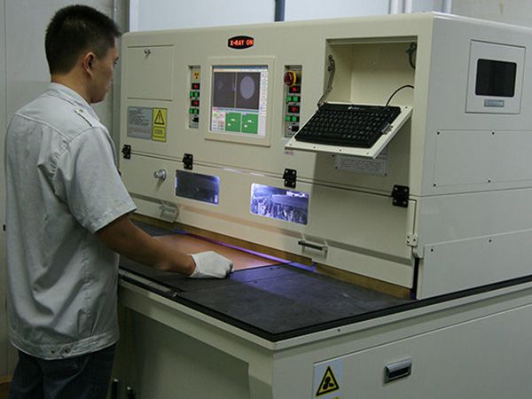
| Testing | 100% electrical test, flying probe (4-wire low resistance), AOI, X-ray, impedance coupon, microsection |
| Lead time | Set per order after engineering reviews your files — a firm date comes back with the quote, normally within one business day. Typical windows below; expedited builds (from 24 h) priced against your deadline. |
Ranges shown are our routine production envelope, not a theoretical maximum. Send the stack-up you actually need and engineering will confirm feasibility — including the parts we would change.
Typical lead times
What "normal" looks like here
These are the windows we hold in routine production, not best-case figures. Every quote carries a firm date against your specific files, and if a build is outside these windows we tell you before you order.
| Board type | Prototype — fabrication time | Production (500+ pcs) — fabrication time |
|---|---|---|
| 2-layer FR-4 | ~5 working days | 2–3 weeks |
| 4–6 layer FR-4 | 7–8 working days | 2–3 weeks |
| 8–10 layer / impedance-controlled | ~15 working days | Quoted per build |
| HDI, high-frequency, rigid-flex & special processes | 18–25 working days | Quoted per build |
Expedited
Need it faster?
For standard FR-4 processes we hold a limited expedited slot each day, priced against your deadline and requirements:
- 2-layerfrom 24 hours
- 4-layerfrom 48 hours
- 6–8 layerfrom 72 hours
Special processes are quoted per build. Send your files with the target date and we'll confirm the same day whether a slot is open — we only promise what the floor can actually hold. These are fabrication times; express transit adds 3–5 days.
All times above are fabrication time only — not the date the boards reach your door. The clock starts when files are released after DFM sign-off. Add 3–5 days for express shipping to the US or EU; your quote states the delivery date at your address.
Layer count & stack-up
A 4-layer control board and a 22-layer backplane are not the same job. Sequential lamination adds press cycles.
Materials
High-frequency and hybrid builds need different lamination profiles and longer conditioning than straight FR-4.
Special processes
Back drilling, castellation, cavities, heavy copper and tight impedance all add dedicated steps.
Finish & quantity
ENEPIG or hard gold take longer than HASL; volume is scheduled against the panel, not the piece count.
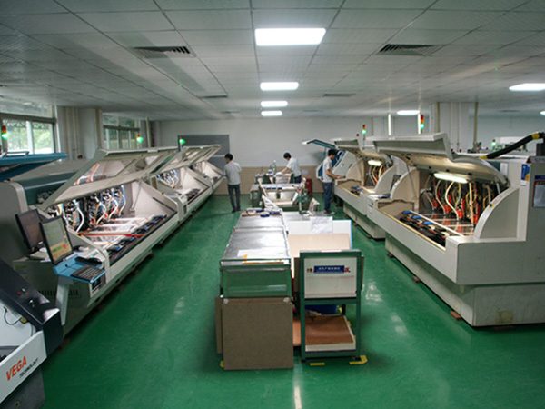
01 — Multilayer FR-4
The bread and butter, done without shortcuts
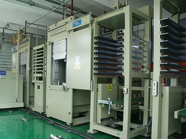
From 4-layer control boards to 22-layer backplanes. Lamination is where a multilayer build is decided — press profiles, bake schedules and incoming laminate are controlled at every stage, so the stack-up holds its dimensions and its electrical performance through assembly and into service.
- High-Tg and thick copperFor thermal cycling and high-current designs; 2 oz and heavier on request.
- Impedance-controlled stack-upsCoupon-verified on every lot.
- Mixed material buildsHigh-frequency cores bonded into an FR-4 stack where the RF section needs it and the budget doesn't allow a full Rogers build.
02 — HDI
Density without yield loss
1 to 3-stage HDI for fine-pitch BGAs, module boards and anything where the component pitch has outgrown the routing space. Laser-drilled microvias, blind and buried vias, resin-plugged via-in-pad — and a DFM pass on pad sizes before tooling starts.
- 1–3 stage buildsUp to 3-stage HDI, with laser microvias, blind and buried vias and resin-plugged via-in-pad.
- Via-in-pad with resin pluggingPlanarized and copper-capped, suitable for thermal pads under QFNs.
- Fine-line imagingLDI exposure in a Class 100,000 cleanroom, on both inner and outer layers.

03 — High-frequency
Rogers where it counts, FR-4 where it doesn't
Full high-frequency builds and hybrid stack-ups: RO4003C, RO4350B, RO3003 or RO4835 bonded to FR-4 or IT180, so the RF section gets the dielectric constant it needs and the rest of the board stays affordable.
- Hybrid laminationPTFE and hydrocarbon cores bonded to FR-4 without delamination at reflow.
- Dk/Df-aware stack-upsImpedance targets verified on coupons made from your actual materials.
- Antenna and RF module boardsTelecom, radar, test equipment and wireless modules.
04 — Rigid-flex & special processes
The orders that need a longer conversation than a price list
Rigid-flex boards, castellated modules, back-drilled high-speed backplanes, metal edge plating, stepped cavities, embedded passives. These are the builds where tooling decisions matter more than price — so we settle them with you before quoting.
- Rigid-flex and flexCoverlay, stiffeners, and controlled bend areas for compact assemblies.
- Module-friendly featuresCastellations, half-holes, countersinks and depth-controlled drilling for SMT modules.
- Back drillingStub removal for high-speed channels, with impedance verification.
From the line
What the work actually looks like
Every board below was built in our plant and photographed on our bench. Layer counts, finishes and materials are as labelled.
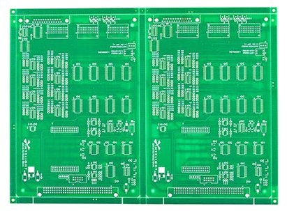
2-layer power board
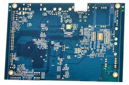
4-layer ENIG board
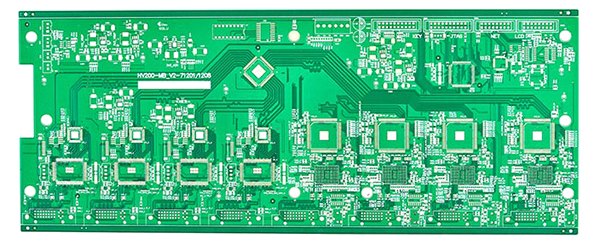
6-layer ENIG board
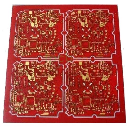
8-layer blind & buried via board
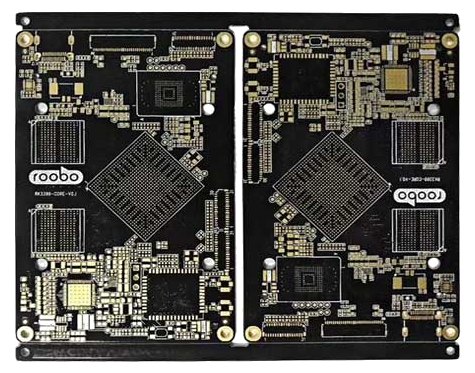
12-layer HDI board
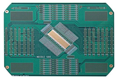
Probe test fixture board
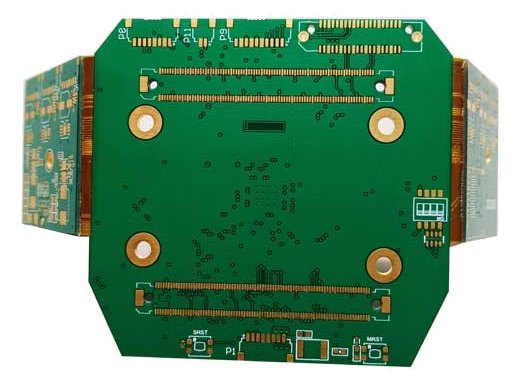
8-layer rigid-flex board
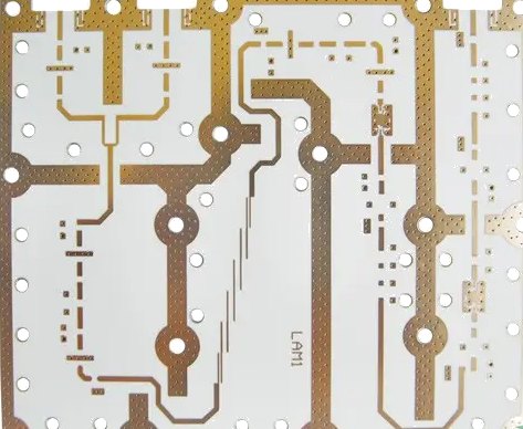
Rogers RO4003C + FR-4 hybrid
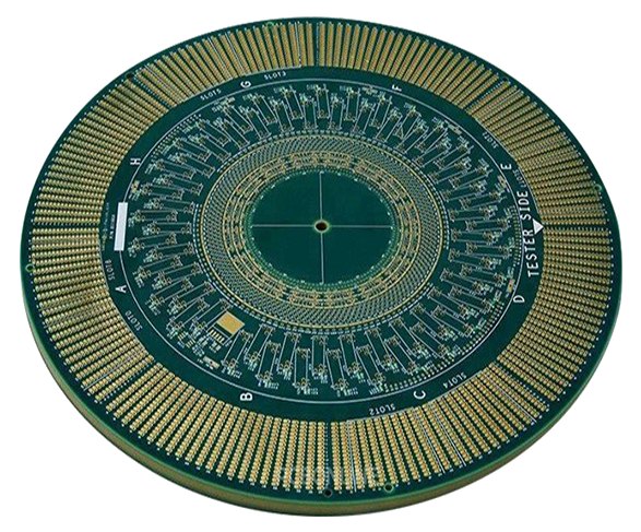
36-layer IC test substrate
Not listed?
If your stack-up isn't on this page, that's usually a conversation, not a no
Send the Gerbers, the material callout and the quantity. Engineering will confirm what's feasible, what isn't, and what we'd change to make it cheaper to build.